- إنضم
- 23 فبراير 2009
- المشاركات
- 7,489
- مستوى التفاعل
- 282
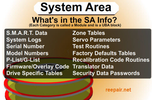
تشريح الهارد ديسك
بسم الله الرحمن الرحيم

مقدمة
بفضل الله سنقوم بإلقاء نظرة سريعه على الهارد ديسك
ومكوناته وبعض النصائح الهامة في الصيانة
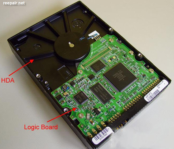
يتكون الهارد ديسك من جزأين أساسين
1- البردة وهي : الجزء خارجي ويطلق
عليه الدائرة المطبوعة(printed circuit board*pcb*) أو logic board
2-الميديا وهي: الجزء الداخلي ويطلق عليه
HDA إختصار لــــ Hard Drive Assembly
كما توضح الصورة التاليه
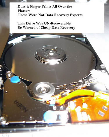
ميديا الهارد لا يمكن التعامل معها بسهولة كالبردة حيث أنها يتم تجميعها في غرف
معقمة ولذا أي تلاعب فيها أو خطأ في فكها غالبا ما يؤدي لتلف الهارد لأن دخول
أي ذرة غبار أو تراب ربما تؤدي لتلف الاسطوانات وسبب ذلك السرعه العالية التي
يدور بها الموتور .
لذلك لا توجد صيانة للميديا الا في بعض المكاتب المتقدمة والمجهزة بما يسمى
clean room
........................
التوصيلات Connectors
تنقسم التوصيلات لأي هارد ديسك إلى قسمين
1- وصلة الباور
2-وصلة الداتا أو ما يسمى interface
ويوجد ثلاث أنواع من وصلات الداتا
ATA =Advanced Technology Attachment)
SATA =Serial ATA
SCSI =Small Computer Systems Interface
وهو منتشر في أجهزة السرفرات حيث السرعات العالية ونادرا ما نجده في الاجهزة العادية.
النوع الأول الهاردات الداتا (ATA=PATA)
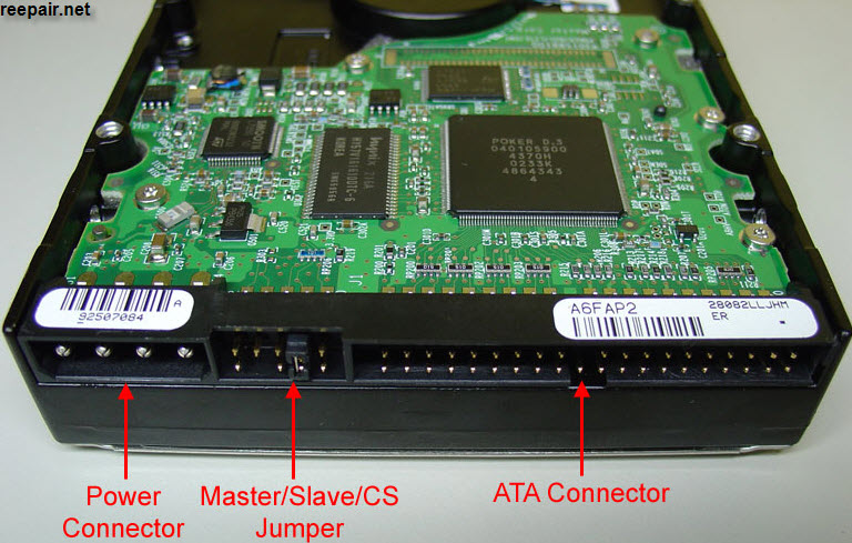
The master/slave jumper on ATA hard drives can be configured in three different ways:
- Master: this means that this drive will be the only one attached to the cable that connects the hard drive to the computer or will be the first drive in a two-drive configuration.
- Slave: this means that this drive will be the second drive attached to the cable that connects the hard drive to the computer.
- CS (Cable Select): this means that you will use a “special” cable (called CS cable) that the configuration of whether a drive will be master or slave will be made by the position of the hard drive on the
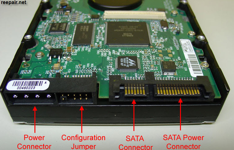
النوع الثاني الساتا SATA
.............
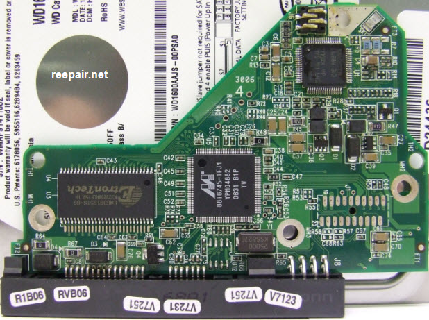
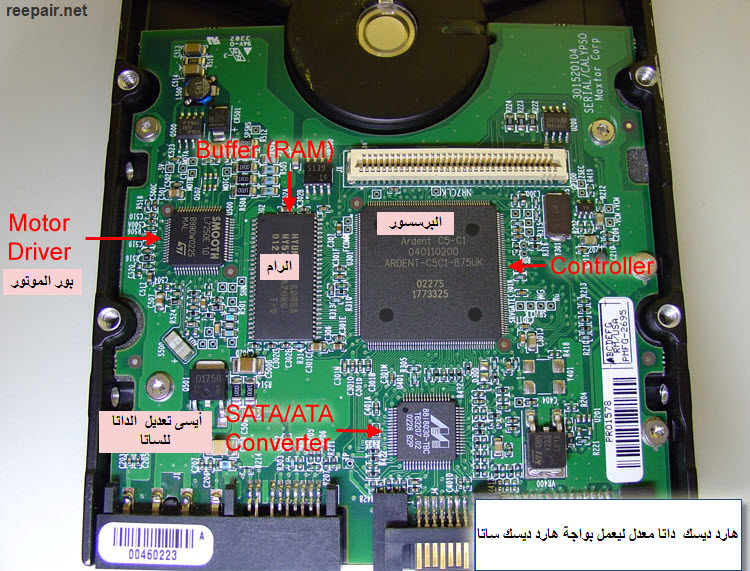
الـبـردة=Logic Board
غالبا ما سنجد من اربعة لخمس دوائر هي التي تتحكم في الهارد وفي الاجيال
الحديثة كالعادة تم دمج بعض الدوائر داخل الشيب (البرسسور) نفسه وسأتناول لاحقا شرحها بالتفصيل ..
مثال على البردة الداتا
Logic board from an ATA hard drive
مثال على البردة الساتا
Logic board from a SATA hard drive
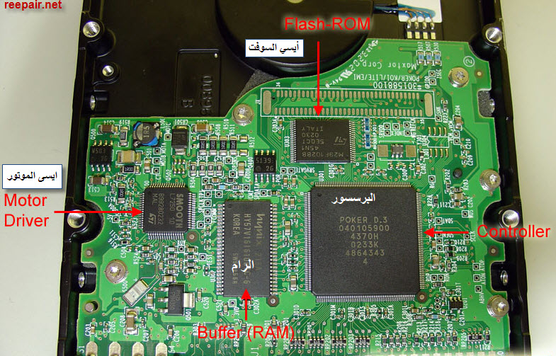
أهم الدوائر الموجودة على البردة
1- البرسسور(controller)
هو الذي يتحكم في كل شيء على البردة مثال ذلك
نقل الداتا بين الهارد ديسك والمعالج
يتحكم في المواتير الموجودة في الهارد ديسك
يوجة الهدود(رؤس الكتابة) من أجل أن تقوم بالكتابة والقراءة على الميديا
وغيرها الكثير من الوظائف
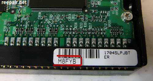
2- أيسى السوفت وير "البيوس" Flash-ROM circuit
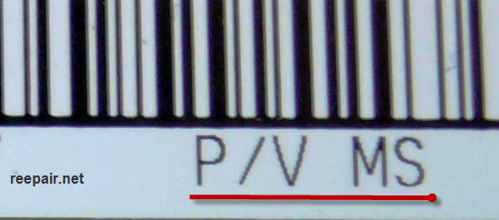
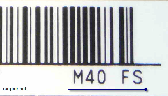
وهي التي يتم تخزين عليها الفيرم وير الخاص بالهارد ويشمل هذا الفيرم وير
التعليمات التي يقوم الكنترولر بتنفيذها بالاضافة لبعض اوامر البنية الهندسية التي
تتشكل بها الميديا.
وفي الهاردات الحديثة يكون مدمج داخل الكنترولر كما توضح الصورة التالية
3-أيسي بور الموتور
نظرا لأن الكنترولر لا يستطيع أن يمد الموتور بالتيار الكافي لدورانة تم تعويض هذا
الفقد بأيسي خاص لبور الموتور( motor driver chip) حيث تقوم تلك الشيب بتكبير التيار current amplifier
وبالتالي فإنه أيس الموتور يتسلم الأمر من الكنترولر ويوصله للموتور بعد أن يتم
تحميله بتيار عالي higher current ولهذا
السبب فانها تقع بين الكنترولر والموتور.
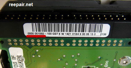
4-الـــــــــرام ( Random Access Memory (BUFFER
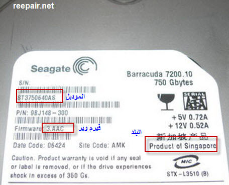
ولها وظيفه محددة على الهارد فكلما كانت سعتها اكبر كلما كان نقل الداتا أسرع
ويمكن معرفة السعه لها عن طريق قراءة الداتا عليها والذهاب لموقع الشركة
المنتجة والبحث هناك بنفس الرقم
SATA/ATA converter chip-5
هذه الشيب كانت موجودة في بدايات ظهور هاردات الساتا والسبب في ذلك هو
تحويل فائض انتاجهم من هاردات الداتا لساتا عن طريق وضع شيب
(converter chip)
ومن أشهر تلك الشيبات Marvell 88i8030
ومع ذلك الهارد له شكل هارد الساتا وأداء هارد الدتا.
..................
الموتور Spindle Motor
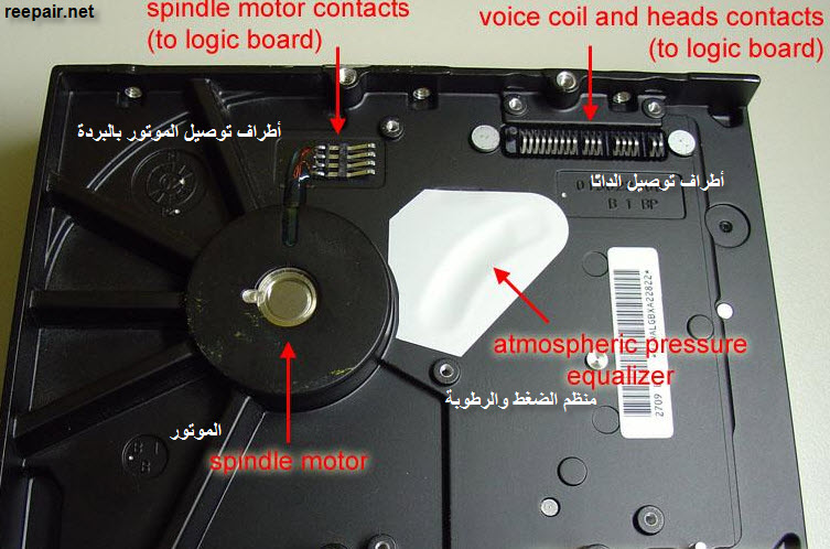
the spindle motor rotates at 5,400 rpm, 7,200 rpm or even 10,000 rpm, depending on the drive. The faster this motor rotates, the faster data can be read from the platters. Hard drives targeted to laptops usually rotates at 4,200 rpm.
.................
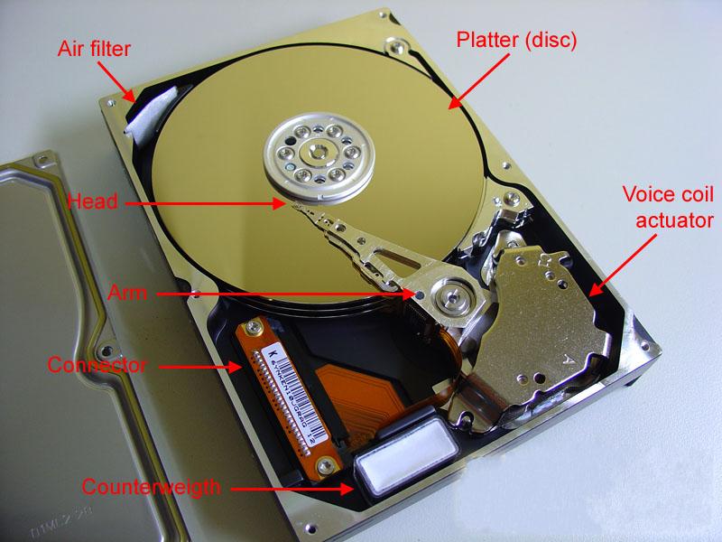
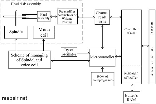
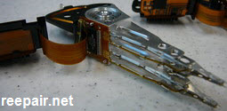
داخل الميديا
كما توضح الصورة مجموعة من الإسطوانات القابلة للكتابة والقراءة في نفس الوقت
والهدود مثبتة معا في ذراع ولذا كل الهدود تتحرك معا.
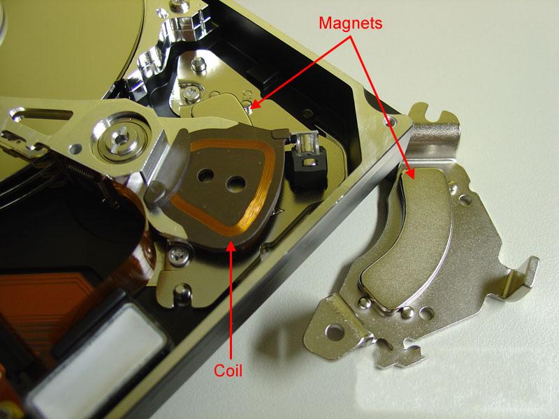
ويقوم الموتور والذي يسمى voice coil بتحريك الذراع وسبب تسمته voice coil لان فكرة عملة هي نفس فكرة عمل السماعات
الملف داخل مجال ممغنط ناتج عن طريق مغناطيس قوي وعن طريق اتجاه التيار
في الملف يتحرك الذراع من اتجاه لاخر وعلى مدى شدة التيار يصل الذراع
لمسافة اكبر أو أقل.
يتبع